Thursday, September 4, 2014

Houdini Great War Frontline v0.6


Another update as tomorrow is my deadline and tonight I managed to, with a gut wrenching nerve in my stomach, create a working digital asset which actually worked the first time around. I made it in a test library but as it did exactly what I wanted I think I'm going to keep it. Tomorrow I'll spend the day adding a metric ton of parameters so the tool is actually usable.

Also, because I'm really tired and don't feel like writing much I'll post a gallery of screenshots I took during the past few days with some explanations in the same format as I used in the previous blogpost.
These two images show that I've created a locator using a box geo to randomly change the location and shape of barracks. Additional parameters manipulate the size of the placement shape and the density of barracks placed on the terrain. To make sure the barracks don't go everywhere I've restricted their spread to between two trenches.


Although spoiled in the first two images, here I take a group selection and use a color attribute to alter the color of that color attribute. After this I transfer the color attribute of just the group selection to the terrain. Purely cosmetic change for presentation.


A quick layout to explain to friends what exactly is going on in the terrain. I think it looks nice and clear enough to post it here as well. The blue lines are the basic trenches, defined by a set of curves. The yellow area is No Man's Land, the piece of land between opposed front lines. The red's are trenches that are dependent on the blue ones. The white is one that is dependent on the red trenches and the the red one in the background wasn't supposed to be red because it's not dependent on anything. The headquarters can be placed independently.


The above two images are intended for comic relief. I accidentally created a loop and saved the file. Instead of using a foreach node I have become accustomed to using a delete node and a copy node with a stamp expression. Unfortunately I made a small mistake and had the copy node refer to a scatter node that spawned 10.000 points. Not cool.


This is how my network looked this afternoon after finishing a clean up. I am using a LOT of object merge nodes to avoid having really long pipes. Also, I like how it looks like a clown network, though I assure you, all colors have meaning. For example, light blue indicates a "prep"-network, dark blue indicates an "edit"-box, purple "selection"-networks and red is either a "necessary evil" or "cleanup"-network.
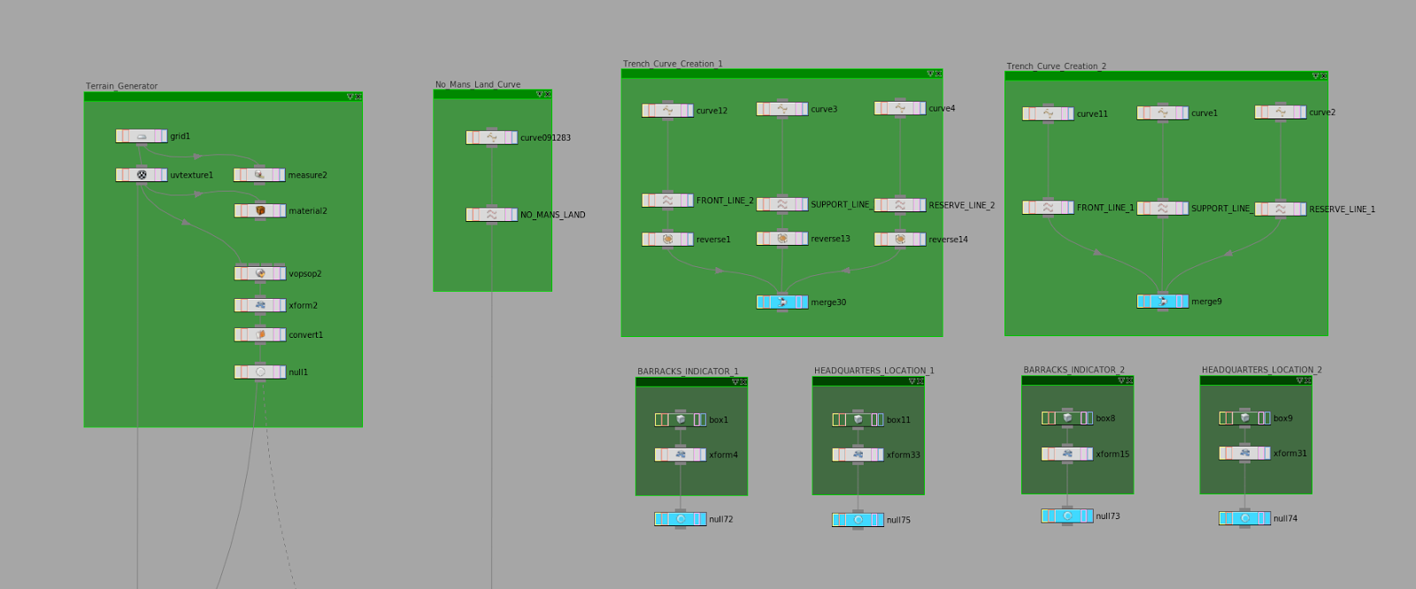

This is a zoomed in image of the input nodes from the network featured in the image above. These are all the inputs necessary for the digital asset I wanted to make. This worried me to no end. How will I ever make a subnet with more than 10 inputs I wondered. This apparently wasn't an issue as a digital asset can have an infinite amount of inputs. Which is absolutely great.


The working system! I cleaned it a little bit and this is how it worked out. All the nodes in the white box are necessary inputs and the ones in the red box are -as mentioned before- "a necessary evil". I also added a little read me node with important information about curve direction, input hierarchy information as having 11 inputs can be fairly confusing and some information concerning build times on my machine.


The result of a build time of 3 minutes and 15 seconds. I've tried various different curve setups and they all manage to work so far. Cooking the geometry takes a long time in my opinion but I'm not sure how to optimize this. In total I think the entire network is close to 4000 nodes of which some extremely heavy subdivide and polyReduce nodes.

  
I think this is a pretty acceptable memory usage. I hope my teach has a similar rig to what I have... or better.

I think tomorrow I'll add some images with different trench shapes. Right now I haven't changed it up much as cooking the geometry every time takes so much time.

Thanks for reading,
Pim

ps. delivery is complete. I managed to get all the parameters in and fixed some other small issues related to radius matching and the likes. If I get a major passing grade I'll think about releasing it to the public. Otherwise nope.

Monday, September 1, 2014

Houdini Great War Frontline v0.5

A little update again as the pressure is now getting to me. The deadline went from unclear to next Friday so I'm working hard to finish this tool. Oorah. In the past few days I managed to pull off the following things; each of which I will precede with an image. I also figured out I could tear off panels in Houdini and work on a dual monitor setup. Silly me.

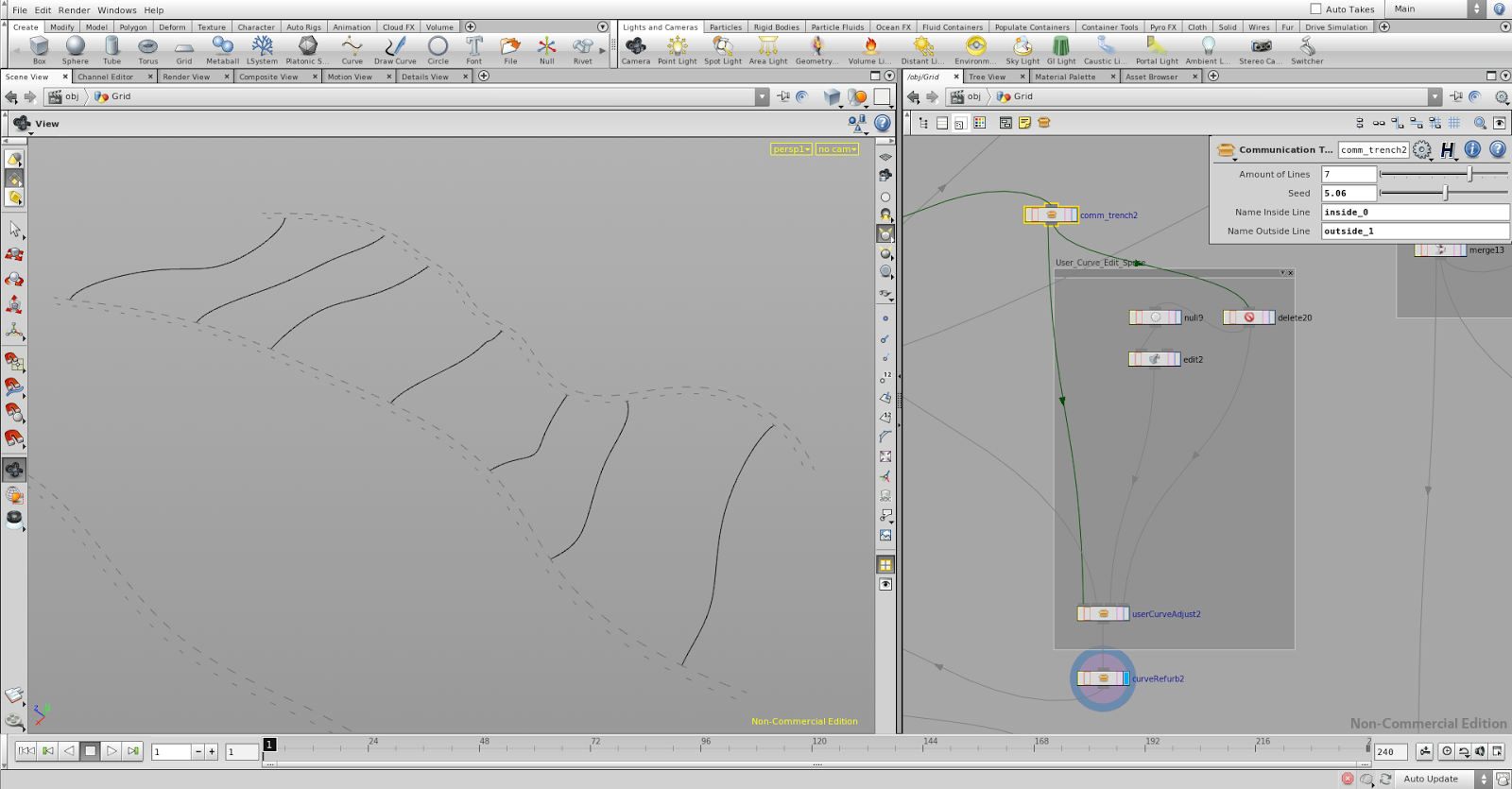
In this instance I was in the process of duplicating the existing trench network and rotating it at it's core. Changing up group names wasn't an issue, though some weird exceptions appeared in a few of the operators. I have also yet to figure out how to make the funk-hole trenches procedural as an exception appears somewhere at the creation of the name spaces.


Here I have sweeped a short line across the trenches and combined the result with the funk-hole circles. The best result presents itself when I extrude the whole shape upward and combine the shapes with a boolean operation called 'cookie'. At this point the downside is, I have to apply this operation to each curve individually -so many different operations- as this cookie node doesn't operate on self-intersecting geometry. 


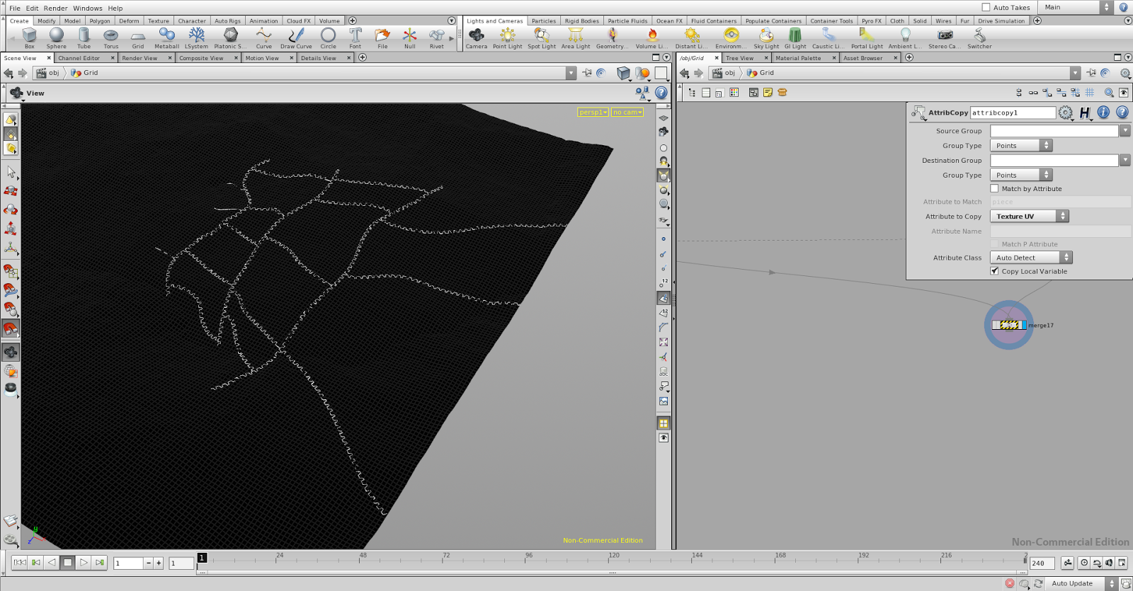
The non-procedural way of ray casting the trench into the terrain. It works fairly well, though somewhere along the line the smooth node's color selection tends to be too small and I get the same effect as a bad filter for when contrast is being added to an image. Both values on each end get pushed; just on the edge of each side a thin line of opposing values gets pushed into the wrong direction, exactly countering what you're trying to achieve.


The procedural way of ray casting the trench into the terrain, though you can see it brings it's own issues. The ray cast is very accurate and on it's own doesn't bring a whole lot of problems with it but when a facet-node is added to recompute the normals I get shading errors. Most likely these are caused by mesh errors. In the image below the shading errors are more apparent.


Clearly very ugly meshing errors. Not sure how I am going to fix this yet.

That was it again. Thanks for reading.
Pim

Monday, August 25, 2014

Houdini Great War Frontline v0.4

The title is only slightly referring to the number of times I've blogged about this subject, but since I find it so fascinating here's another one. I figured a monthly blog update is pretty sweet especially since this project is running into its final week (hopefully) and next week I'm going to start a whole new one win a completely different area.

Next week I'm entering the "specialization" phase of my education. The penultimate course of my education which allows me to fully surround myself with software I've hardly or never had the chance of working with before.

But for now, screenshots below of my progress and small notes in which I explain what's going on. You'll notice much has been cleaned and many more subnet's have been placed in a 'for each' kind of node setup using stamp functions in Delete and Copy nodes. I've had help from a friend and colleague at Grid-VFX. 


The Original Curve. Dictates the placement of No Man's Land. The piece of land between two opposing forces, usually surrounded by a trench. The term is mostly commonly associated with the First World War.


Application of the Original Curve. The flattened land is almost unnoticeable in the top left corner of this image but work wonders for the trench curves that are projected onto the surface later. Especially the SAP's (forward listening posts) are prospering in flatter area's as they're short in length and don't feature a stepped pattern.

>
The Front-line, Support Trench and Reserve Trench are now three separate curves combined in a merge node. After the merge a delete with a stamp expression and a copy node repeat the operations located between the two to mimic the operations of a 'for each' node. A trench digital asset does the rest.


After this, a friend helped me out with creating a selection set that I would be able to use indefinitely for each collection of trench curves, given that I precede it with a digital trench asset. Between the selected curved I spawn a number of curves using the parameter in the top right part of the image. The random seed changes the direction and strength of its control points but.. the real trick is being able to adjust the end points of each individual curve to adjust it's direction. The curvature is preserved and the curves never intersect, unless you spawn thirty of them.


Both the placement of SAP's and additional reserve trenches have been applied in this image. The SAP's are created by duplicating the front-line trench in order to maintain their direction; which is pointing at the opposing trench. The same concept is applied to the additional reserve trenches but I used a group selection to cut off the parts of the trench I don't need as it falls out of the 'combat zone'; as dictated by the bounding box of the terrain.


Today I've been bug fixing mostly. Some of which didn't make much sense and others that seemed to be so incredibly persistent on just, for example, the second primitive in a sequence that the easiest solution would have simply been to adjust just the second primitive and leave the rest as is... Coincidentally this is what I did and I've tried a least a dozen completely different input expression to try to break it but it won't anymore. I can't get over how weird Houdini is sometimes, though I guess somewhere it has to make sense.

For next time I want:

  • Funk holes and dugouts between communication trenches the same way as the communication trenches are currently located between the regular trenches. However, they must not connect to the other side and cannot end in a linear fashion.
  • Sweep across each individual curve with a previously created shape. Invert all three curves and calculate their curve points against the Original Curve's curve point positions to create an opposing trench network with the same customization as the original one.


That's it again. Not much time left on this project. Hopefully I can finish these things before I hand it in!

Thanks for reading,

Pim

Friday, August 1, 2014

Astérix Le Domaine Des Dieux, Houdini Great War Frontline and SolidAngle Arnold

Some time has passed and since I didn't write anything last month I figured I'd give it another go. During these past few weeks it has become clear that the production I have been working on is on schedule and will air in French cinema's around November 27th. So as far as I know I am totally allowed to tell you what it is!  Yay!

So I've been working on "Astérix: Le Domaine Des Dieux"; in English "Asterix: The Mansion of the Gods". Unfortunately the IMDB page is empty but there's an unofficial Facebook page which you can go ahead and like. At least I think it's unofficial... I'm not sure... Oh well. Here are some promotional posters.


So in my last blog update I wrote about duplicated curve projections on a procedural landscape and some problems that arose with the technique I used. Firstly it wasn't entirely procedural and secondly it featured a gigantic node system; one that could be easily fit into multiple Digital Assets. Below a duplication of what my comments were on the progress I had made and how I addressed them with the help of a colleague and friend.


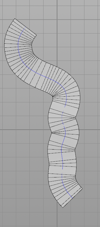
  • Create non-stretched UV's for the additional 3 sweeped curves using the length of the line used for the sweep and the measured length of the curve.


  • In the copy node above I output 7 curves which I blend between a blendshape node like you would in Maya, however each curve of my output will be added to it's own separate group. Using a blast node I can now select the copyGroup I need and delete the rest (non-selected). This will then allow me to measure the curve along it's length and apply accurate UV's onto a sweeped mesh. This happens later.


  • Ability to adjust the sweep distance for each individual curve so I can determine the amount of land they smooth out.

  • This turned out to be a different issue than I had first anticipated as it didn't just incorporate the sweeping distance; it would also incorporate the size and shape of the trench. In the first image of the previous paragraph a solution is already present in the shape of a trenchnet digital asset.


    I used an L-system to create a curve that would allow me to duplicate it along a resampled curved but with the premise that the L-system curve's size would be the same as the distance between two adjacent points on a resampled curve. I achieve this by adding a transform node that uses the following expression in the Uniform Scale attribute:

    (1/bbox("../lsystem#",D_YSIZE))*ch("../resample#/length")
    The first part normalizes the bounding box volume of the L system and the second part multiplies it with the edge length determined by the resample node. Then I add normals, copy the l-system along the curve and clean up until I have something I desire.

    Below are some examples of the shapes it can take on in it's current state of development. I'm contemplating whether I should add a few more functions like degradation and additional offset, but for now I'm satisfied.


    A three dimensional result of the above with a sweep looks pretty sweet.


  • Find a way to get rid of the holes that are currently created in the landscape mesh. I know these are created by a group selection a tiny bit back up the selection creation grouping but I can't seem to figure out how to make that selection smaller.

  • This is one where I had to do the exact opposite and increase the reference instead of decreasing the size of the selection to avoid it taking point positions from a location that was not correct yet.

    The solution was to take the curve that creates the height of the reference mesh and increase it along it's own normals by creating a vector between the last and second-to-last point. This is high school math where using an if statement (compare node) calls both the top result as the one below as an output. The normalize node at the end makes sure that we're extending the normal of the curve at the same rate.


  • Create a polygonal bridge between the existing sweeps so I can create a selection for the area's between the trenches. This may become handy for the distribution of details later.

  • This one... I didn't think this through as it's not something I would like to have. I think it would be much better to use the bounding shape of the trench to sweep across the curve and act as a smoother for the landscape than to have a whole general area that flattens everything. Not a fan of this idea anymore. Going to do it differently.


    For now the most difficult step will be to find a way to have all the different trenches connect to one another. I will definitely update this blog as soon as I have a solution for that... And that was it for Houdini. But I did do some other stuff also!

    I can't keep my hands off of Arnold. Such a great rendering tool. Even crappy light setups can turn out to be great physically correct calculations. I also discovered this amazing website with free high quality models ready for everyone to render.


    I specifically want to add that the two renders above are not an exercise in my lighting capabilities but more of a test whether I want to use Arnold for my graduation phase. I'll be starting my specialization soon and I'd like to know some render engine specific things before I even start researching software and hardware packages.

    Anyways, that was it. Thanks a lot for reading!
    Pim

    ps. Arnold coming to Houdini? The best of both worlds? GWAAAAAAaaaaaaa

    Tuesday, June 17, 2014

    Houdini - Duplicating curves

    Since the last update on the procedural terrain I have been trying to duplicate my original curve into several others religiously but without much success. The internet overall had been of little help with this as in most solutions the premise was to simply create another curve. So instead of creating a curve I decided to UV all my surfaces and combine the result into the final mesh.

    Simple projection
    Projection with a measure and curve length calculation for non-stretched UV's.
    For the duplication of the curve I tried various different methods of which nodes like the ForEach, wireBlend and copy gave me the best results. However, they didn't allow me the bend the curve farther away with each instance and so they weren't what I was going to use. Then -magically- a colleague approached me after reading this blog and sent me a file in which he had made a small example scene with a curve, a VOPSOP with several point to point calculations and a blendShape node that would blend the copies between the two -in this case- 'blend to' nodes. This was a fantastic solution which I was able to incorporate immediately.

    Turns out the sweep node has a 'group output' check box which I am going to use for unique UV sets for the amount of sweeped curves I'm projecting, though I still have an issue using the measure node to calculate the exact length of each individual curve. Somewhere along the way my copyGroups from the copy node are going missing and I can't refer to them anymore.

    The interpolation of the duplicates from the copy node is calculated using the in- and output of the VOPSOP.
    Stretched mapping as the UV calculation is using only the length of the first curve.
    Holes in the surface where the group selection only calculates the height of the vertices of the lower located mesh.

    Another few things I definitely want to apply before I start building the trenches are:
    • Create non-stretched UV's for the additional 3 sweeped curves using the length of the line used for the sweep and the measured length of the curve.
    • Ability to adjust the sweep distance for each individual curve so I can determine the amount of land they smooth out.
    • Find a way to get rid of the holes that are currently created in the landscape mesh. I know these are created by a group selection a tiny bit back up the selection creation grouping but I can't seem to figure out how to make that selection smaller.
    • Create a polygonal bridge between the existing sweeps so I can create a selection for the area's between the trenches. This may become handy for the distribution of details later.
    That was it again. Thanks for reading.
    Pim

    Tuesday, June 10, 2014

    Great War Frontline in Houdini

    My internship is awesome and since it's coming to an end I guess I can go into a little more detail than I did before. I haven't signed NDA's for everything but I'm still trying to be as careful as I can, obviously.

    I touched compositing on two series and was allowed to do some vfx on one of those also. I baked animation caches and wrangled with shots for a little over two weeks with so much troubleshooting I filled two 200-paged notepads. Learned a metric ton about why this stuff can go so wrong and since end of February I've been working on a full feature film which name I unfortunately can't mention. At least... I think that's what the NDA I signed said. Better safe than sorry.

    Save the practical knowledge, I've also learned so much about film pipeline I can't fathom to think I could remember it all in a month's time. Fortunately I've been keeping a day journal and summarizing everything I'm picking up here and there so I can visualize what has passed my way. Working with Linux every day, talking to all the talented people at Grid and being allowed far more responsibility than I had first anticipated really pays off. I feel like a sponge; continually collecting knowledge.

    But anyways, now that's covered I'll follow this up with some stuff I've been working on this weekend. I might have mentioned before that I still have a school related retake left to do and as this weekend was a long one where our team didn't have to do any overtime I figured it would be a nice opportunity to start my Houdini project. During the past couple of weeks I've also managed to squeeze some time into PFTrack, Boujou, Matchmover, Composite, Fusion and Nuke, but nothing quantifiable has come from those efforts. Just a lot of stuff that's really not worth showing.

    A while ago I went about and wrote this big document in which I explained the how and what. In case you are interested in reading this document, you can contact me via mail. Below are some samples of what you'll find in it.


    Sources to the information gathered in this document are covered in a list that occupies the last two pages.


    During this weekend I managed to create a procedural displacement map, but realized I could also do it in a VOPSOP as it offers the same nodes as the VOPCOP. I was also told it would be much faster if I'd create my height map in the same geo group but I haven't been able to crosscheck this with my scene. Both compile almost immediately unless I increase my grid size with a factor twenty. Then it won't compile at all.


    Displacement map in VOPCOP
    For the image below I used an anti-alias noise node on top of a cell noise node to create this hilly landscape. The cell noise node allows me to make it really flat (almost countryside-like) or change the spectrum entirely and go mountainous. The anti-alias noise node allows for an uneven landscape and offers different noise option to tone it. Then I thought it would be cool add rivers by creating a veins node.

    Displacement map in VOPSOP
    What comes after this is taken from a lecture posted on YouTube by my teacher, Kim Goossen, as it is a well documented way of projecting curves on a surface, creating a point selection tool out of this and smoothing surfaces using color id's created with attributes. Next to this he also takes the effort to troubleshoot certain problems that occur during this and offers different ways of achieving the same result.

    Curvesweep point selection.


    Color ID'd to calculate the size and height of the final points.
    I am currently looking into a way to copy my original curve to create three parallel curves to each side and bend their ends away by using a parabola function per control point. So far with the help of a friend I've come to the function below... though I'm pretty sure this won't work for each point as I've only managed to get two correct solutions out of it. The rest were off by decimals.

    y = ((x-(n/2)+1)²) / 4

    It is still not correct however and I'm leaning towards using a different method (which has been suggested by a different friend) that would assist me in reaching the same solution otherwise. Still, I really want to make this function work and apply it to my curves. Would be great to see it work.


    As a final to this wall of text I want to refer to my previous blogpost where I addressed the idea for a short. After giving it some thought I've figured it's better too look ahead but not too far. Each idea that looks like a great one often turns out to be one I don't want to finish. My best bet for now is to write each one down, fool around and learn as much as I can to properly visualize what I am capable of finishing in half a year than to be going with each fantastical idea. It's a sad realization but a necessary one.

    Anyways, that was it for now. Updates are long and far apart but they'll keep coming.

    Thanks for reading,
    Pim

    ps. as icing on the cake I was offered my first real industry job at Grid for the summer holiday! Weeee! Not sure what my job title will be but it'll be awesome regardless! I should totally celebrate.