Another update as tomorrow is my deadline and tonight I managed to, with a gut wrenching nerve in my stomach, create a working digital asset which actually worked the first time around. I made it in a test library but as it did exactly what I wanted I think I'm going to keep it. Tomorrow I'll spend the day adding a metric ton of parameters so the tool is actually usable.
Also, because I'm really tired and don't feel like writing much I'll post a gallery of screenshots I took during the past few days with some explanations in the same format as I used in the previous blogpost.


These two images show that I've created a locator using a box geo to randomly change the location and shape of barracks. Additional parameters manipulate the size of the placement shape and the density of barracks placed on the terrain. To make sure the barracks don't go everywhere I've restricted their spread to between two trenches.


A quick layout to explain to friends what exactly is going on in the terrain. I think it looks nice and clear enough to post it here as well. The blue lines are the basic trenches, defined by a set of curves. The yellow area is No Man's Land, the piece of land between opposed front lines. The red's are trenches that are dependent on the blue ones. The white is one that is dependent on the red trenches and the the red one in the background wasn't supposed to be red because it's not dependent on anything. The headquarters can be placed independently.

The above two images are intended for comic relief. I accidentally created a loop and saved the file. Instead of using a foreach node I have become accustomed to using a delete node and a copy node with a stamp expression. Unfortunately I made a small mistake and had the copy node refer to a scatter node that spawned 10.000 points. Not cool.

This is how my network looked this afternoon after finishing a clean up. I am using a LOT of object merge nodes to avoid having really long pipes. Also, I like how it looks like a clown network, though I assure you, all colors have meaning. For example, light blue indicates a "prep"-network, dark blue indicates an "edit"-box, purple "selection"-networks and red is either a "necessary evil" or "cleanup"-network.
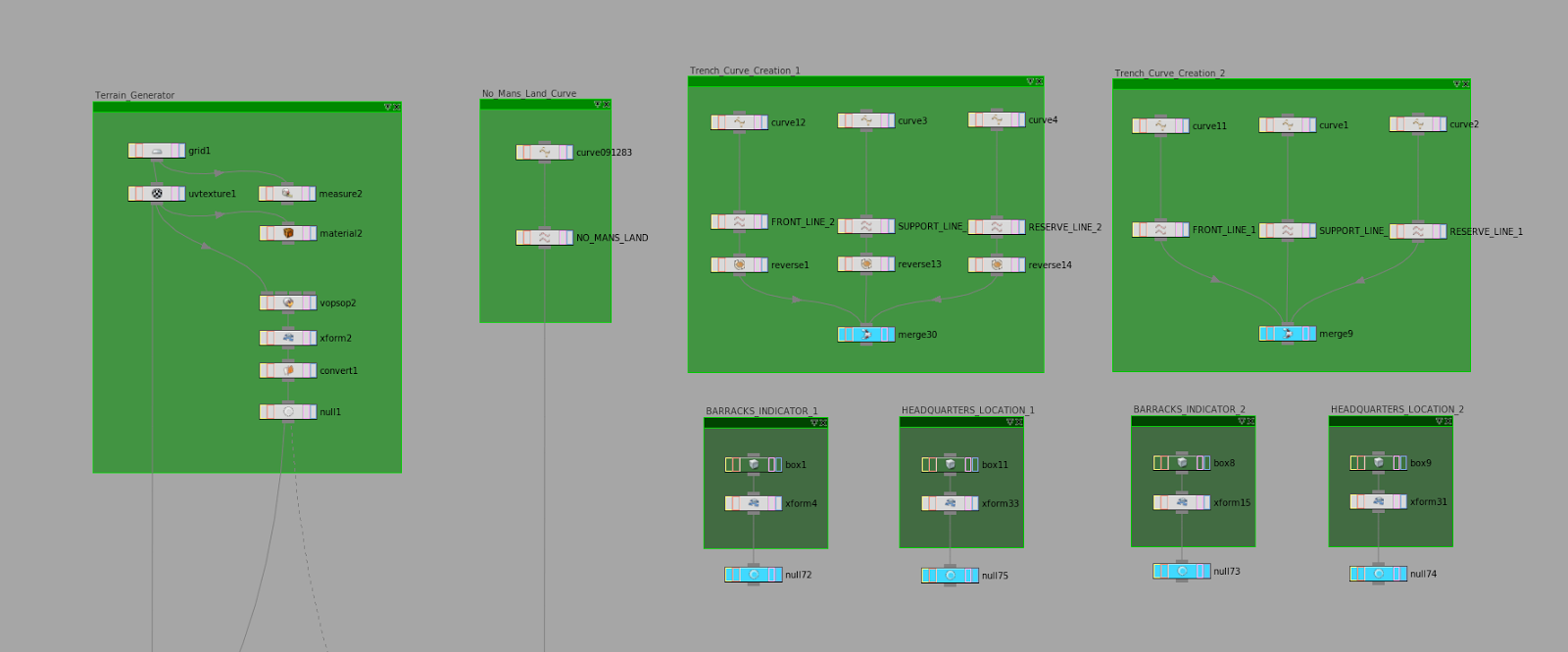
This is a zoomed in image of the input nodes from the network featured in the image above. These are all the inputs necessary for the digital asset I wanted to make. This worried me to no end. How will I ever make a subnet with more than 10 inputs I wondered. This apparently wasn't an issue as a digital asset can have an infinite amount of inputs. Which is absolutely great.

The working system! I cleaned it a little bit and this is how it worked out. All the nodes in the white box are necessary inputs and the ones in the red box are -as mentioned before- "a necessary evil". I also added a little read me node with important information about curve direction, input hierarchy information as having 11 inputs can be fairly confusing and some information concerning build times on my machine.

The result of a build time of 3 minutes and 15 seconds. I've tried various different curve setups and they all manage to work so far. Cooking the geometry takes a long time in my opinion but I'm not sure how to optimize this. In total I think the entire network is close to 4000 nodes of which some extremely heavy subdivide and polyReduce nodes.

I think tomorrow I'll add some images with different trench shapes. Right now I haven't changed it up much as cooking the geometry every time takes so much time.
Thanks for reading,
Pim
ps. delivery is complete. I managed to get all the parameters in and fixed some other small issues related to radius matching and the likes. If I get a major passing grade I'll think about releasing it to the public. Otherwise nope.


